Author: Vincent Jackson

How does the lightweight nature of ceramic board benefit installation and handling?

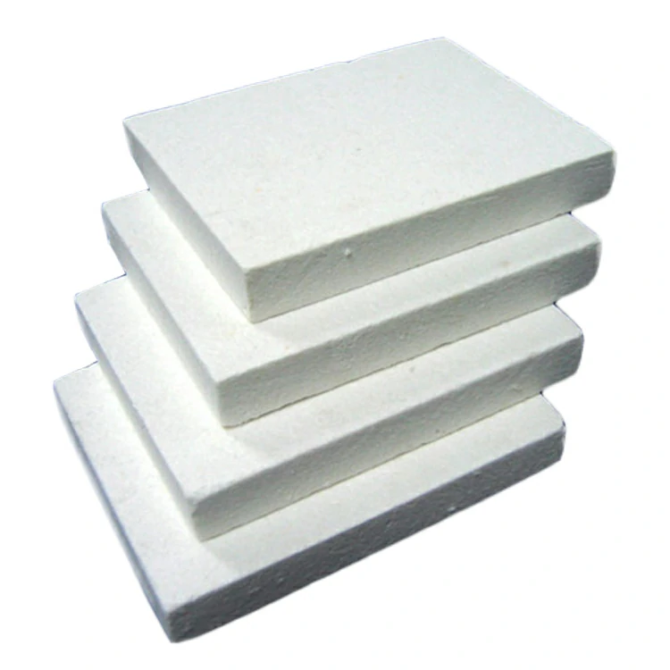
The lightweight nature of ceramic boards offers several benefits for installation and handling:

  1. Ease of Transportation: Ceramic boards are significantly lighter than traditional refractory materials such as bricks or castables. This lightweight characteristic makes them easier to transport from the manufacturer to the installation site, reducing shipping costs and logistical challenges.
  2. Reduced Labor Requirements: Handling lightweight ceramic boards requires less physical effort compared to heavier materials. Installers can maneuver and position the boards more easily, reducing the need for heavy lifting equipment or additional labor assistance during installation.
  3. Faster Installation: The lightweight nature of ceramic boards enables quicker and more efficient installation processes. Installers can work more rapidly, cutting, shaping, and fitting the boards into place without experiencing fatigue or strain from handling heavy materials. This results in shorter installation times and reduced labor costs.
  4. Improved Safety: Lightweight ceramic boards pose less risk of injury during handling and installation compared to heavier materials. There is a reduced likelihood of strains, sprains, or accidents caused by lifting heavy loads, enhancing overall safety for installers and workers on the job site.
  5. Ease of Cutting and Shaping: Ceramic boards can be easily cut, shaped, and drilled using standard tools such as saws or drills. Their lightweight nature allows for precise cutting and manipulation, facilitating customization to fit complex or irregularly shaped surfaces without requiring specialized equipment or expertise.
  6. Versatility in Design: The lightweight nature of ceramic boards allows for greater design flexibility in construction and engineering projects. ceramic board They can be used in a variety of applications, including walls, floors, ceilings, and enclosures, without adding excessive weight or structural strain to the building or equipment.
  7. Minimized Structural Load: Ceramic boards impose minimal structural load on buildings, structures, or equipment where they are installed. Their lightweight construction reduces the overall weight-bearing requirements, potentially lowering construction costs and simplifying engineering design considerations.
  8. Ease of Retrofitting: Lightweight ceramic boards are well-suited for retrofitting existing structures or equipment. Their ease of handling and installation allows for straightforward integration into pre-existing systems, minimizing disruption to operations and reducing downtime during renovation or maintenance projects.

Overall, the lightweight nature of ceramic boards offers numerous advantages for installation and handling, including ease of transportation, reduced labor requirements, faster installation, improved safety, ease of cutting and shaping, versatility in design, minimized structural load, and ease of retrofitting. These benefits make ceramic boards an attractive choice for a wide range of industrial, commercial, and residential applications.

What makes ceramic fiber insulation resistant to high temperatures and thermal shock?

Ceramic fiber insulation exhibits exceptional resistance to high temperatures and thermal shock due to its unique composition and structural properties. Here’s how:

  1. High Melting Point: Ceramic fiber insulation is primarily composed of alumina-silicate fibers, which have an exceptionally high melting point. These fibers can withstand temperatures ranging from 1260°C to 1800°C (2300°F to 3272°F), making them ideal for applications where extreme heat is encountered.
  2. Low Thermal Conductivity: Ceramic fiber insulation has low thermal conductivity, meaning it does not transfer heat efficiently. Instead, it acts as a barrier to heat transfer, minimizing the amount of thermal energy that can penetrate through the insulation material.
  3. Excellent Thermal Stability: Ceramic fiber insulation maintains its structural integrity and insulation properties even when exposed to high temperatures for prolonged periods. It does not degrade or deteriorate at elevated temperatures, ensuring long-lasting performance in demanding thermal environments.
  4. Minimal Thermal Expansion: Ceramic fiber insulation exhibits minimal thermal expansion, meaning it expands very little when exposed to heat. This property reduces the risk of thermal stress and cracking, even during rapid temperature changes or thermal cycling.
  5. Resistance to Thermal Shock: Ceramic fiber insulation is highly resistant to thermal shock, which occurs when a material undergoes rapid temperature changes. ceramic fiber insulation The inherent flexibility and resilience of ceramic fibers allow them to withstand sudden shifts in temperature without cracking or breaking, ensuring reliable performance in thermal cycling applications.
  6. Structural Stability: Ceramic fiber insulation maintains its structural stability and dimensional integrity at high temperatures, providing consistent insulation performance over time. It does not shrink, warp, or deform under thermal stress, ensuring a tight seal and effective insulation in critical applications.
  7. Chemical Inertness: Ceramic fiber insulation is chemically inert and resistant to chemical reactions, even at high temperatures. It does not react with most chemicals or gases, ensuring that its insulation properties remain unaffected in corrosive or aggressive environments.
  8. Versatility: Ceramic fiber insulation is versatile and can be tailored to suit specific temperature requirements and application needs. It is available in various forms, including blankets, boards, papers, and modules, allowing for flexibility in design and installation in a wide range of industrial and commercial applications.

Overall, the combination of high melting point, low thermal conductivity, thermal stability, resistance to thermal shock, structural integrity, and chemical inertness makes ceramic fiber insulation exceptionally resistant to high temperatures and thermal cycling, making it an ideal choice for demanding thermal insulation applications.

How does the triple offset butterfly valve maintain its sealing properties over time?

The triple offset butterfly valve maintains its sealing properties over time through several design features and mechanisms:

  1. Offset Disc Design: Unlike traditional butterfly valves, the triple offset design features an offset disc that rotates around its own axis as well as the valve stem axis. This offset design allows the sealing surface of the disc to contact the seat only at the final stage of closing, minimizing wear and reducing the likelihood of friction-induced damage to the sealing surfaces.
  2. Metal Seating Surfaces: Triple offset butterfly valves often use metal-to-metal seating surfaces, typically made from materials such as stainless steel or hard alloys. These materials offer excellent resistance to wear, corrosion, and high temperatures, ensuring long-term sealing performance even in demanding applications.
  3. Soft Seating Inserts: Some triple offset butterfly valves incorporate soft seating inserts made from materials like elastomers or PTFE (polytetrafluoroethylene) on the sealing surfaces. triple offset butterfly valve These inserts provide a tight seal while also offering resilience and flexibility to accommodate minor misalignments, ensuring consistent sealing performance over time.
  4. High-Quality Construction: Triple offset butterfly valves are manufactured to high precision standards, ensuring tight tolerances and smooth operation. This quality construction minimizes the potential for leaks and ensures reliable sealing properties throughout the valve’s service life.
  5. Robust Actuation Systems: Proper actuation systems, such as pneumatic, electric, or hydraulic actuators, are essential for maintaining sealing properties over time. These systems provide precise control over the valve operation, minimizing stress on the sealing components and ensuring consistent performance.
  6. Corrosion Resistance: Many triple offset butterfly valves are designed with corrosion-resistant materials and coatings to withstand aggressive media and harsh operating environments. This resistance to corrosion helps preserve the integrity of the sealing surfaces and prolongs the valve’s sealing properties.

Overall, the combination of offset disc design, high-quality materials, precise construction, and robust actuation systems enables triple offset butterfly valves to maintain their sealing properties over time, providing reliable performance in a wide range of industrial applications.

What are the potential failure modes of the u type butterfly valve?

Several potential failure modes of a U-type butterfly valve include:

  1. Leakage: One of the most common failure modes is leakage, which can occur due to issues such as improper seating of the valve disc, wear or damage to the sealing surfaces, or deterioration of sealing materials over time.
  2. Sticking or Binding: The valve disc may become stuck or bind within the valve body, preventing it from opening or closing properly. This can happen due to debris accumulation, corrosion, or misalignment of the disc and seat.
  3. Corrosion: Corrosion of the valve body, disc, or other components can occur, particularly if the valve is exposed to corrosive fluids or environments. Corrosion weakens the structural integrity of the valve and can lead to leaks or mechanical failure.
  4. Wear and Erosion: Components of the valve, such as the disc, seat, shaft, and seals, can experience wear and erosion over time, especially if the valve is subjected to high flow rates, abrasive media, or frequent cycling.
  5. Shaft Failure: The shaft connecting the actuator to the valve disc may experience failure due to bending, fatigue, or shearing, u type butterfly valve especially if it is undersized or if excessive torque is applied during operation.
  6. Actuator Failure: The actuator responsible for opening and closing the valve may fail to operate properly due to issues such as mechanical failure, electrical or pneumatic system malfunctions, or insufficient power supply.
  7. Cavitation: In applications where the fluid velocity is high, cavitation can occur, causing damage to the valve internals due to the formation and collapse of vapor bubbles. This can lead to erosion, vibration, and ultimately failure of the valve components.
  8. Seal Degradation: Seals used in the valve, such as O-rings or elastomeric seat materials, can degrade over time due to exposure to temperature extremes, chemical attack, or mechanical stress, leading to leakage or loss of sealing integrity.

To mitigate these potential failure modes, regular inspection, maintenance, and proper installation of the U-type butterfly valve are essential. Additionally, selecting the appropriate materials and design considerations based on the specific operating conditions can help minimize the risk of failure.

What considerations should be made when selecting materials for concrete coil nails in humid or corrosive environments?

When selecting materials for concrete coil nails in humid or corrosive environments, several important considerations should be made to ensure optimal performance and longevity:

  1. Corrosion Resistance: The primary consideration is selecting materials with high corrosion resistance properties, especially in humid or corrosive environments. Stainless steel, particularly grades like 304 or 316, is highly resistant to corrosion and is often the preferred choice for concrete coil nails in such conditions.
  2. Galvanized Coating: Another option is to use galvanized coatings on steel nails. Hot-dip galvanized or electroplated zinc coatings provide an additional layer of protection against corrosion, extending the lifespan of the nails in humid or corrosive environments.
  3. Material Compatibility: Ensure that the selected material is compatible with concrete and other materials commonly used in construction. Compatibility issues can lead to galvanic corrosion, compromising the integrity of the fastening system.
  4. Exposure Conditions: Consider the specific exposure conditions in which the concrete coil nails will be used. Factors such as exposure to saltwater, chemicals, or industrial pollutants can accelerate corrosion. Choose materials that can withstand these conditions effectively.
  5. Environmental Regulations: Ensure compliance with environmental regulations and restrictions on the use of certain materials. For example, some regions have restrictions on the use of certain coatings or materials due to environmental concerns.
  6. Durability and Lifespan: Prioritize materials that offer durability and a long lifespan, even in harsh environmental conditions. Investing in high-quality materials may initially cost more but can result in significant savings over the long term by reducing maintenance and replacement costs.
  7. Testing and Certification: Verify that the selected materials meet relevant industry standards and certifications for corrosion resistance. concrete coil nails Look for products that have been tested and certified by reputable organizations to ensure their performance in humid or corrosive environments.
  8. Surface Treatment: Consider surface treatments or coatings that can enhance the corrosion resistance of the nails. For example, additional sealants or protective coatings can provide an extra layer of defense against moisture and corrosive agents.
  9. Maintenance Requirements: Evaluate the maintenance requirements associated with different materials. Choose materials that require minimal maintenance and upkeep to ensure long-term performance in humid or corrosive environments.
  10. Cost Considerations: Balance the cost of materials with their performance and longevity. While corrosion-resistant materials may have a higher upfront cost, they can provide significant savings in the long run by reducing the need for frequent replacements and maintenance.

By considering these factors when selecting materials for concrete coil nails in humid or corrosive environments, you can ensure that the fastening system remains durable, reliable, and resistant to corrosion over time.

How do manufacturers ensure the consistency of material properties across different batches of stainless steel coil roofing nails ?

Ensuring consistency of material properties across different batches of stainless steel coil roofing nails is crucial for maintaining product quality and performance.

Manufacturers employ several strategies to achieve this:

  1. Supplier Qualification: Manufacturers carefully select suppliers of stainless steel coil roofing nail materials based on their reputation, quality control processes, and adherence to industry standards. Establishing long-term partnerships with reliable suppliers helps maintain consistency in material properties.
  2. Material Specifications: Manufacturers define strict material specifications outlining the required chemical composition, mechanical properties, and quality standards for stainless steel coil roofing nail materials. These specifications serve as benchmarks for evaluating material consistency across different batches.
  3. Quality Assurance Procedures: Rigorous quality assurance procedures are implemented throughout the manufacturing process to verify material properties and ensure compliance with specifications. This includes incoming material inspection, in-process quality checks, and final product testing to detect any deviations from established standards.
  4. Batch Testing and Sampling: Manufacturers conduct batch testing and sampling of stainless steel coil roofing nail materials to assess material consistency across different production runs. Samples are taken from each batch and subjected to comprehensive testing to verify key material properties, such as tensile strength, hardness, and corrosion resistance.
  5. Process Control Measures: Tight process control measures are implemented to minimize variability and maintain consistency in material properties during manufacturing. This includes monitoring and controlling factors such as temperature, pressure, alloy composition, and production parameters to ensure uniformity across batches.
  6. Statistical Process Control (SPC): Manufacturers utilize statistical process control techniques to monitor and analyze production data in real-time. By monitoring process variables and identifying trends or deviations from expected norms, stainless steel coil roofing nails manufacturers can take corrective actions promptly to prevent inconsistencies in material properties.
  7. Traceability Systems: Robust traceability systems are implemented to track the origin and history of stainless steel coil roofing nail materials throughout the supply chain. This enables manufacturers to trace and identify any issues or discrepancies in material properties back to the source and take corrective actions as needed.
  8. Continuous Improvement Initiatives: Manufacturers continuously seek opportunities to improve material consistency through process optimization, technology upgrades, and employee training initiatives. By investing in continuous improvement efforts, manufacturers can enhance control over material properties and minimize variability across batches.
  9. Certifications and Standards Compliance: Manufacturers adhere to relevant certifications and industry standards governing the production of stainless steel coil roofing nail materials. Compliance with standards such as ASTM International, ISO, and ANSI ensures that material properties meet established quality and performance requirements.
  10. Customer Feedback and Monitoring: Manufacturers solicit feedback from customers and monitor product performance in the field to identify any issues related to material consistency. Customer feedback serves as valuable input for refining manufacturing processes and addressing potential concerns related to material properties.

By implementing these strategies, manufacturers can ensure the consistency of material properties across different batches of stainless steel coil roofing nails, thereby maintaining product quality, reliability, and customer satisfaction.

How do control wafer butterfly valve characteristics impact their performance in industrial control systems?

The characteristics of control wafer butterfly valves have a significant impact on their performance in industrial control systems. These valves are widely used for regulating fluid flow in various industrial processes.

Here are key characteristics and their effects on performance:

  1. Flow Control Precision:
    • The ability to precisely control fluid flow is a crucial characteristic. Control wafer butterfly valves, when properly designed, can offer precise and modulating control, allowing operators to adjust flow rates according to specific process requirements.
  2. Linear Flow Characteristics:
    • Some control wafer butterfly valves are designed to exhibit linear flow characteristics, meaning that the relationship between valve position and flow rate is relatively linear. This is desirable for accurate and predictable control in industrial processes.
  3. Quick Response Time:
    • The response time of the valve to control signals is critical for dynamic processes. Control wafer butterfly valves with fast response times ensure rapid adjustments to changes in flow requirements, contributing to the agility of industrial systems.
  4. Turndown Ratio:
    • The turndown ratio represents the range over which a valve can effectively control flow. Control wafer butterfly valves with a high turndown ratio can handle a wide range of flow rates, providing flexibility in adapting to varying process conditions.
  5. Stability in Partial Load Conditions:
    • The stability of control in partial load conditions is important for processes with variable flow requirements. Control wafer butterfly valves should maintain stability and accuracy even when operating at less than full capacity.
  6. Leakage Prevention:
    • The design of control wafer butterfly valves should minimize the risk of leakage when the valve is in the closed position. Effective sealing is crucial to prevent unwanted fluid leakage and maintain the integrity of the process.
  7. Durability and Reliability:
    • The materials and construction of control wafer butterfly valves impact their durability and reliability. In harsh industrial environments, valves need to withstand corrosion, abrasion, and wear to ensure long-term performance with minimal maintenance requirements.
  8. Temperature and Pressure Ratings:
    • Control wafer butterfly valves should be selected based on their temperature and pressure ratings to ensure they can operate safely and effectively within the specified range of the industrial process.
  9. Materials Compatibility:
    • The compatibility of materials with the fluids being processed is essential. Control wafer butterfly valves should be constructed from materials that resist corrosion and chemical degradation, wafer butterfly valve ensuring compatibility with the substances flowing through the system.
  10. Automation Compatibility:
    • The ability to integrate control wafer butterfly valves into automation and control systems is crucial for modern industrial processes. Compatibility with digital control systems allows for centralized monitoring, adjustment, and optimization of the entire system.
  11. Fail-Safe Features:
    • Some control wafer butterfly valves come with fail-safe features, such as fail-open or fail-closed mechanisms. These features enhance the safety and reliability of the industrial system in the event of a power outage or control system failure.
  12. Cavitation and Aeration Resistance:
    • Control wafer butterfly valves should be designed to resist cavitation and aeration effects, particularly in applications where these phenomena can occur. Proper design mitigates potential damage and ensures stable control.

In summary, the characteristics of control wafer butterfly valves impact their performance in industrial control systems by influencing flow control precision, response time, stability, leakage prevention, durability, materials compatibility, temperature and pressure ratings, automation compatibility, fail-safe features, and resistance to cavitation and aeration. Selecting valves with appropriate characteristics is essential for achieving optimal performance and efficiency in industrial processes.

What role do manifold dual disc check valve play in simplifying and optimizing fluid control in industrial systems?

Manifold dual disc check valves play a crucial role in simplifying and optimizing fluid control in industrial systems by providing effective flow regulation, preventing backflow, and ensuring system reliability.

Here are several key roles these valves play:

  1. Backflow Prevention:
    • Manifold dual disc check valves are designed to prevent the backflow of fluids in industrial systems. By allowing flow in one direction only, these valves protect downstream equipment, pipelines, and processes from contamination or damage that could result from reverse fluid flow.
  2. Reduced Pressure Drop:
    • The design of manifold dual disc check valves minimizes pressure drop across the valve during forward flow. This characteristic ensures that the system operates with efficient energy transfer, reducing energy losses and maintaining optimal pressure levels.
  3. Compact Design and Space Efficiency:
    • Manifold valves often have a compact and space-efficient design. This is particularly beneficial in industrial systems where space constraints are a concern. The manifold configuration allows multiple check valves to be integrated into a single unit, optimizing space utilization.
  4. Simplified Installation and Maintenance:
    • The manifold design simplifies the installation process, as it allows for the consolidation of multiple check valves into a single assembly. This reduces the number of individual components, streamlining installation procedures. Additionally, maintenance becomes more straightforward, as a single manifold unit can be inspected and serviced more efficiently than multiple individual valves.
  5. Versatility in Application:
    • Manifold dual disc check valves are versatile and suitable for a wide range of industrial applications. They can be used in various fluid types, temperatures, and pressure conditions, making them adaptable to diverse industrial processes.
  6. Cost Savings:
    • The integration of multiple check valves into a single manifold unit can result in cost savings. It reduces the need for purchasing and installing individual valves, as well as the associated piping and fittings. dual disc check valve Moreover, streamlined maintenance can contribute to lower operational costs over time.
  7. High Flow Capacity:
    • Manifold dual disc check valves are designed to handle high flow capacities. This is essential in industrial systems where large volumes of fluid need to be transported or processed, ensuring efficient and continuous operation.
  8. Durability and Long Service Life:
    • These valves are constructed with durable materials to withstand the harsh conditions often encountered in industrial environments. The robust design contributes to a long service life, reducing the frequency of replacements and associated downtime.
  9. Compatibility with Automation:
    • Manifold dual disc check valves can be integrated into automated control systems. This compatibility allows for remote monitoring and control, enhancing the overall efficiency of fluid control in industrial processes.
  10. Optimized System Performance:
    • By preventing backflow, minimizing pressure drop, and simplifying fluid control, manifold dual disc check valves contribute to optimized system performance. This ensures that industrial processes run smoothly and efficiently, meeting operational requirements and minimizing disruptions.

In summary, manifold dual disc check valves simplify and optimize fluid control in industrial systems by preventing backflow, reducing pressure drop, offering a space-efficient design, simplifying installation and maintenance, providing versatility, offering cost savings, handling high flow capacities, ensuring durability, and being compatible with automation. These valves are valuable components in industrial applications where reliable and efficient fluid control is paramount.

How are updates and upgrades managed for the wet wipe’s software and hardware?

Managing updates and upgrades for the wet wipe lid capping machine’s software and hardware involves a systematic and careful approach to ensure seamless integration and optimal performance.

Here’s a comprehensive overview:

Software Updates:

  1. Version Control System:
    • Implement a version control system for the software to track changes, enhancements, and bug fixes systematically.
  2. Remote Monitoring and Diagnostics:
    • Enable remote monitoring capabilities to assess the machine’s performance and identify potential software issues.
    • Implement diagnostic features that allow real-time troubleshooting and analysis.
  3. Software Patching:
    • Develop a process for releasing software patches to address minor issues or security vulnerabilities without requiring a full software upgrade.
  4. User Interface (UI) Updates:
    • Consider user feedback and industry advancements to improve the user interface and overall user experience.
    • Provide clear instructions and documentation for users on updating the software.
  5. Compatibility Testing:
    • Before releasing updates, conduct thorough compatibility testing to ensure that the new software version works seamlessly with existing hardware and other components.
  6. Automated Updates:
    • Integrate an automated update mechanism to streamline the software update process, allowing users to easily download and install the latest versions.
  7. Security Updates:
    • Regularly release security updates to protect the machine from potential vulnerabilities and cyber threats.
  8. Customer Communication:
    • Establish effective communication channels to inform customers about upcoming updates, including the benefits and any potential changes to the machine’s operation.
  9. Backup and Recovery Plans:
    • Implement robust backup and recovery mechanisms to safeguard data and settings during software updates, minimizing the risk of data loss.

Hardware Upgrades:

  1. Modular Design:
    • Design the machine with a modular architecture to facilitate the replacement or upgrade of specific hardware components without disrupting the entire system.
  2. Compatibility Checks:
    • Prior to hardware upgrades, perform compatibility checks to ensure that the new components are compatible with existing software and other hardware.
  3. Documentation:
    • Provide comprehensive documentation outlining the process for hardware upgrades, including step-by-step instructions, wet wipe label for baby recommended components, and potential challenges.
  4. Training Programs:
    • Offer training programs for operators and maintenance personnel to ensure they are proficient in installing and replacing hardware components.
  5. Lifecycle Management:
    • Establish a lifecycle management strategy for hardware components, outlining the expected lifespan and recommended upgrade paths.
  6. Field Service Support:
    • Provide field service support to assist customers in implementing hardware upgrades, if necessary.
  7. Supply Chain Collaboration:
    • Collaborate with suppliers to ensure a steady supply of compatible replacement parts and upgraded components.
  8. Testing and Validation:
    • Rigorously test new hardware components to validate their performance and reliability before recommending them as upgrades.
  9. Product Roadmap:
    • Develop a product roadmap that outlines future hardware upgrades and improvements, keeping customers informed about the evolution of the machine.
  10. Regulatory Compliance:
    • Ensure that any hardware upgrades comply with relevant industry regulations and safety standards.

By adopting a proactive and systematic approach, manufacturers can manage software and hardware updates effectively, ensuring that the wet wipe lid capping machine remains current, secure, and performs optimally over its lifecycle.

How is the machine’s compatibility with different wet wipe lid sizes ensured?

Ensuring the machine’s compatibility with different wet wipe lid sizes involves several steps and considerations to accommodate variations in lid dimensions. Here’s an explanation:

  1. Adjustable Components: The machine may feature adjustable components such as guides, clamps, or holders that can be easily modified to accommodate different lid sizes. This adaptability allows the machine to handle a range of dimensions.
  2. Modular Design: The machine might be designed with a modular structure, allowing specific modules or sections to be replaced or adjusted according to the size requirements of the wet wipe lids. This modularity enhances flexibility.
  3. Programmable Settings: If the machine is automated, it may have programmable settings that can be configured for different lid sizes. This programming could include adjustments for positioning, sealing pressure, and other relevant parameters.
  4. Tooling Changes: The machine may have interchangeable tooling or molds that can be switched out to match the specifications of various lid sizes. This enables efficient production changes without requiring extensive reconfiguration.
  5. Sensors and Feedback Systems: Sensors may be incorporated into the machine to detect the dimensions of incoming lids. Feedback systems can then automatically adjust the machine settings to ensure proper handling and sealing based on the lid size.
  6. Testing and Validation: Prior to production runs with new lid sizes, the machine may undergo testing and validation processes. This involves running trials with different sizes to confirm that the machine can consistently and accurately handle each variation.
  7. Customer Input and Customization: If the machine is designed to be customizable, customers may provide specifications for their specific lid sizes. wet wipe lid capping machine The machine can then be configured or customized during the manufacturing process to meet these requirements.
  8. Documentation and Guidelines: The machine’s documentation, including user manuals and technical guides, may include instructions on how to adjust and configure the machine for different lid sizes. This ensures that operators have the necessary information to make appropriate adjustments.
  9. Quality Control Checks: Quality control procedures may include checks for proper lid placement, alignment, and sealing for each size. Regular inspections during production help identify any issues related to compatibility and ensure consistent quality.
  10. Collaboration with Lid Manufacturers: Collaboration between the machine manufacturer and lid producers can facilitate the alignment of machine specifications with industry-standard lid sizes. This ensures that the machine is built to accommodate commonly used dimensions.

By incorporating these measures, manufacturers can establish a wet wipe lid capping machine that is versatile and capable of handling various lid sizes efficiently and accurately.